ELPIS Smartwatch
Summary
- Envisioned and developed a simple smartwatch based on a 32-bit ARM Cortex M0+ microcontroller from Atmel (ATSAML21) which connects to an Android device (using Bluetooth) to provide useful features and information for the user.
- Managed all aspects of the project such as prototyping, circuit building, PCB designing, 3D modeling, searching for the appropriate electrical and mechanical components from distributors like Digikey and Mouser, hardware and mechanical design, system UI/UX, and the general aesthetics of the device.
- Developed the embedded software for the watch in C using Atmel Studio.
- Developed an Android app written in Java using Android Studio which allows the user to communicate with the watch over Bluetooth.
About the Project
Smartwatches are complex and highly optimized devices which contain some of the most advanced consumer technologies available today. They offer useful information and functionality right on our very wrist but can be quite expensive. So, over the 2 months of summer holidays (July-August) in 2015 I began working on creating a simple smartwatch with a simple and intuitive user interface.
The design goal of this project was to create a smartwatch which does not use any unnecessary (for me) gimmicks and can last for at least a week on a single charge. The device needed to communicate with an Android device to show any relevant notifications, incoming phone calls or messages.
The initial prototype for the watch was based on the Arduino framework in order to test the functionality of the various components needed in the watch. A significant amount of work was done in refining the software on the watch and the smartphone. I also learned how to use the Eagle CAD PCB Design package so that I could create custom PCBs and reduce the size of the watch. I meticulously searched various electrical component distributors (such as Digikey and Mouser) to find components for the watch which were also within my handling and soldering capabilities. I worked through various iterations of the hardware and conducted many experiments to refine the user experience and the ways in which the user can interact with the smartwatch. However, my progress on this project slowed down and became intermittent once I started my 3rd year of classes. I gained a great amount of experience in electric circuit design, PCB designing and 3D modeling during my 8-month co-op work term at Robert Bosch GmbH (Stuttgart, Germany). Using this experience, I have further refined the design of the electric circuit, the PCB and the housing of the watch. I have also decided to upgrade from an Arduino based system to a more power efficient 32-bit microcontroller from Atmel. However, my progress was halted again due to a 16-month stretch of classes and co-op jobs. Now that I have finally finished my degree, I have started working on this project again. I am currently getting close to building a near final prototype of the hardware after which I will continue to refine the software.
Prototyping
The first iteration of this project started as an Android based system. I started off by creating a porotype setup using an Arduino Uno and the various other components I wanted to use in the project on a breadboard.
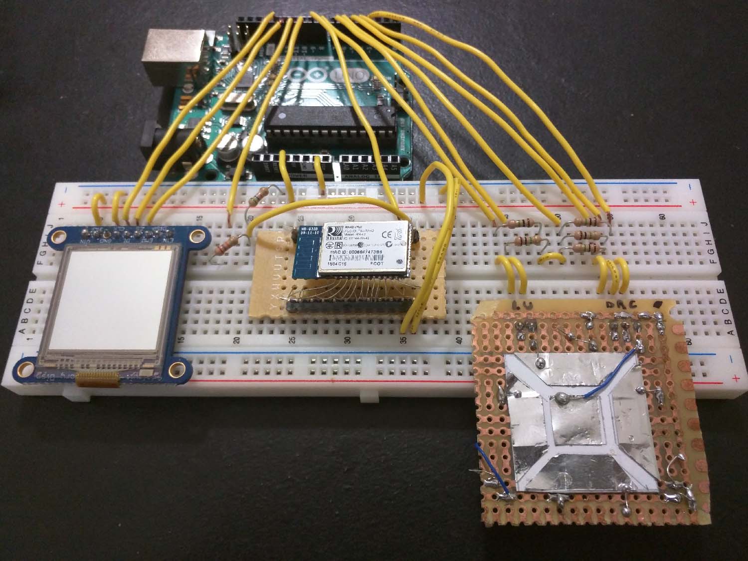
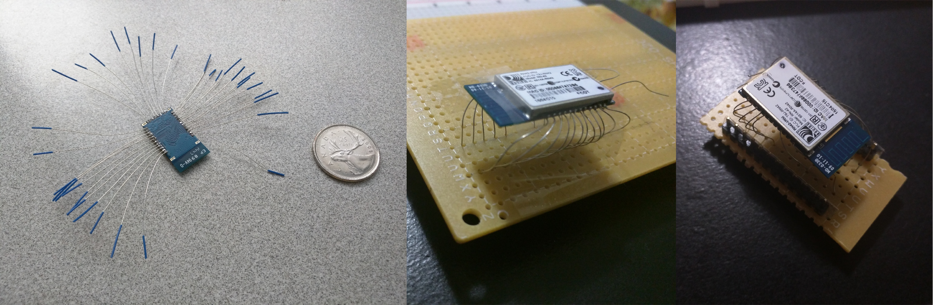
However, I had made the mistake of ordering SMD Bluetooth modules without any breakout boards. This meant that I had to face significant trouble in trying to use the Bluetooth module on a breadboard. However, I was able to solder thin wires to the pins on the module and solder them to a perf board where it could then be used on a breadboard.
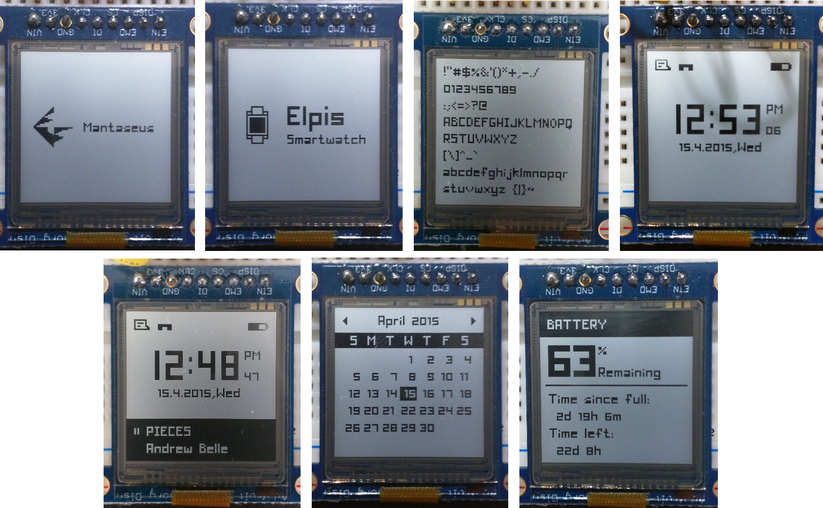
On the software side, I developed Arduino libraries for manipulating the pixels on the display, write text to the display, showing various types of information on the display, transmit and receive data from the Bluetooth module, etc.
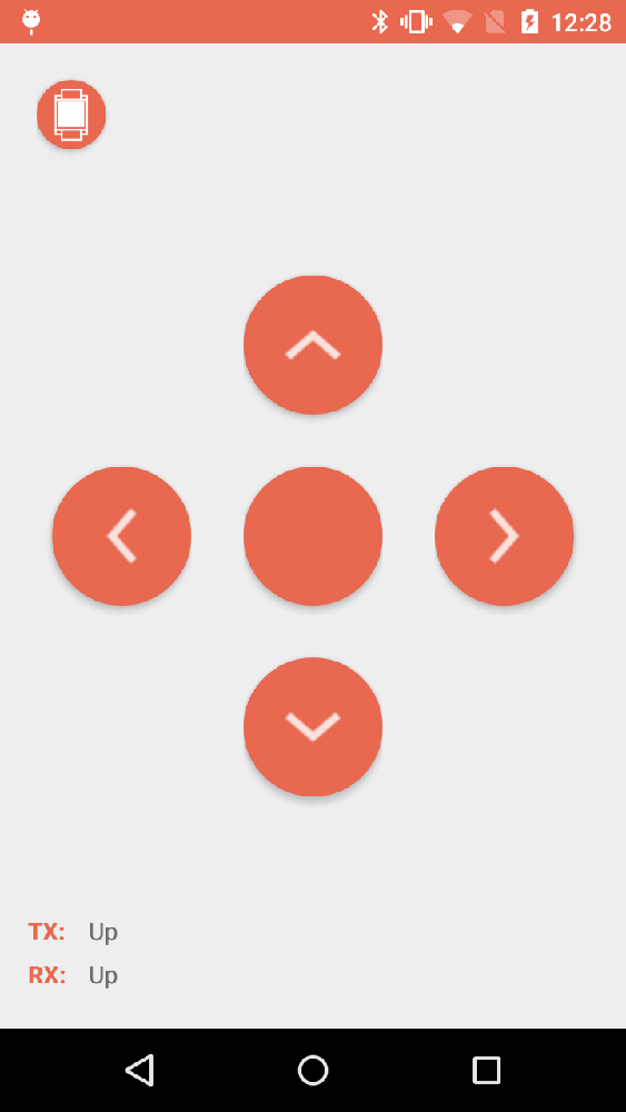
I also developed an Android app which would connect to the Bluetooth module on the prototype and allow me send and receive commands from the device. I could wirelessly change the time being displayed by the smartwatch, update the music information on the smartwatch as the music changes on the phone, use the smartwatch to change the volume and music on the phone, etc. At this time, I did not have any physical buttons on the smartwatch. So, I simulated commands from the physical buttons by sending the command to the smartwatch from the phone and making the smartwatch send the appropriate contextual command back to the phone.
My main goal with this prototype was to understand if I could actually create a compelling UI for the display. However, as I continued to develop the software on the watch, I realized that the 16MHz clock speed, the 8-bit AVR architecture, and limited hardware peripherals of an Arduino chip were simply not enough to drive the 96x96 pixel display graphics with a smooth frame rate. Therefore, after doing extensive research, I decided to use the 32-bit ARM Cortex-M0+ based Atmel SAM L21 as the main controller chip on the smartwatch.
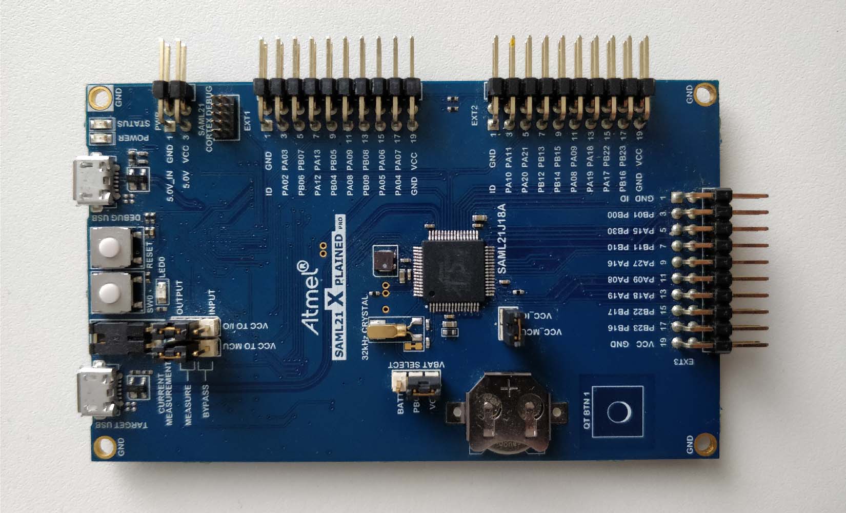
When I got back to the project in 2017, I decided to change my prototype setup to use an ATSAML21 development board. I ported the Arduino libraries that I had created for the Arduino IDE into Atmel Studio and used the new powerful hardware to make various performance improvements to the code.
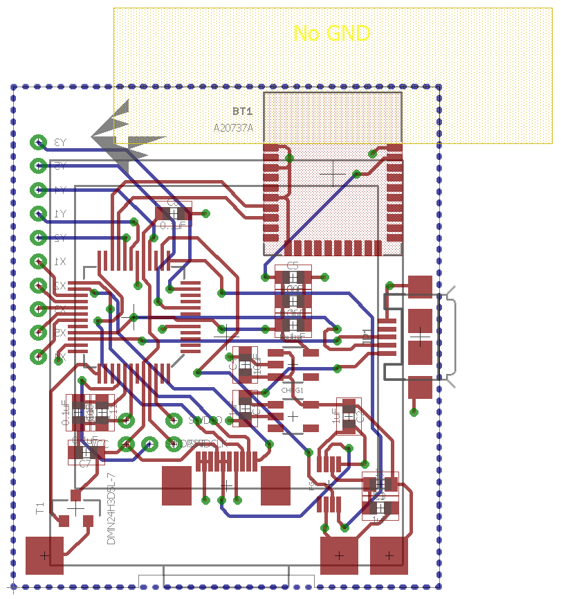
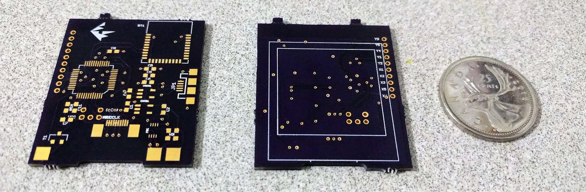
PCB Design
Throughout this project, I made various revisions to the smartwatch design and the components used within the smartwatch. This is because I tried to work on this project in my spare time while I was still going through my Mechatronics degree. Many times, I had to put the project on hold because of my academic workload or co-op work terms. Every time I came back to the project, I had gained new knowledge which forced me to redesign the smartwatch so that it would perform better and be more efficient. The PCB design was the one of the various aspects of this project that got the most changes after every intermission.
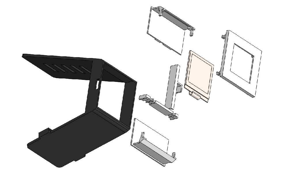
Enclosure Design
Similar to the PCB design, the enclosure has also undergone various design changes over the years. The original enclosure design tried to integrate relatively complex home made directional switch system which gave the device a huge 50mm x 50mm footprint. However, the most recent iteration of the design uses a clear ITO coated plastic layer to provide a touch interface. The enclosure is designed to be 3D printed by a dual material 3D printer (which is already available to me) and has an area of conductive material which will act as capacitive touch buttons for user navigation.
The enclosure design is still under development and is likely to change in the future as well.
Achieving Low Power Consumption
One of the key components that have allowed me to pursue my lofty battery life goals is the SHARP Memory LCD display which only uses 4μA at 3.3V and has built-in memory retention so that data transmission to the display only needs to take place when we want to make changes to the display. The SHARP Memory LCD has similar power consumptions as an e-ink display but has the high refresh rate (up to 60Hz) of an LCD. This, along with it’s relatively small memory buffer requirement allows me to be significantly more power efficient.
The Atmel SAM L21 MCU also contributes to the low power consumption of the smartwatch by only using approximately 35μA / MHz in active mode. This means that the MCU only uses around 1.5mA when running at 48MHz (it’s maximum clock speed) in active mode. In this project, the MCU might only need to stay in active mode for a few milliseconds every second (to process time and update the display). ATSAML21 has various sleep modes such as idle, standby, backup and off modes which allow the MCU to use less energy by turning off certain peripherals. By properly switching between active and sleep mode, the smartwatch has become even more power efficient.