Flexo-line Braiding Machine (Capstone Project)
Summary
- Worked with 3 other team members to create a braiding machine that can braid three elastic strands of Latex with finite length (i.e. no spools) to help FlexoLine increase the production and quality of their travel clotheslines
- Designed the mechanical structure of the device in SolidWorks
- Sourced electrical components and motors
- Designed and constructed the electrical circuit which controls the operation of the whole machine
- Wrote code in C++ for the microcontroller (Teensy 3.2) to use feedback data from motor encoders to synchronize the motion of various motors used in the machine
- Wrote a Windows .NET application in C# to control and monitor the performance of the machine
About Capstone Projects
In the fourth and last year of our Engineering degree, we are required to take part in a Capstone project. A capstone project is an 8 month long project where the students work within teams to solve the engineering needs of real life clients. It is the culmination of our engineering studies and allows us to showcase the knowledge and skills we have learned throughout the course of our degree.
In the beginning of the fourth year, we were given information about nearly 50 different project and were asked to rank our preferred projects. The faculty of mechanical engineering tried to assign students to their preferred projects as best as possible depending on availability. Once we were given a particular project, a professor from the faculty of mechanical engineering was also assigned to us as our supervisor in order to guide us through the project.
About the Client: Flexo-Line Co.
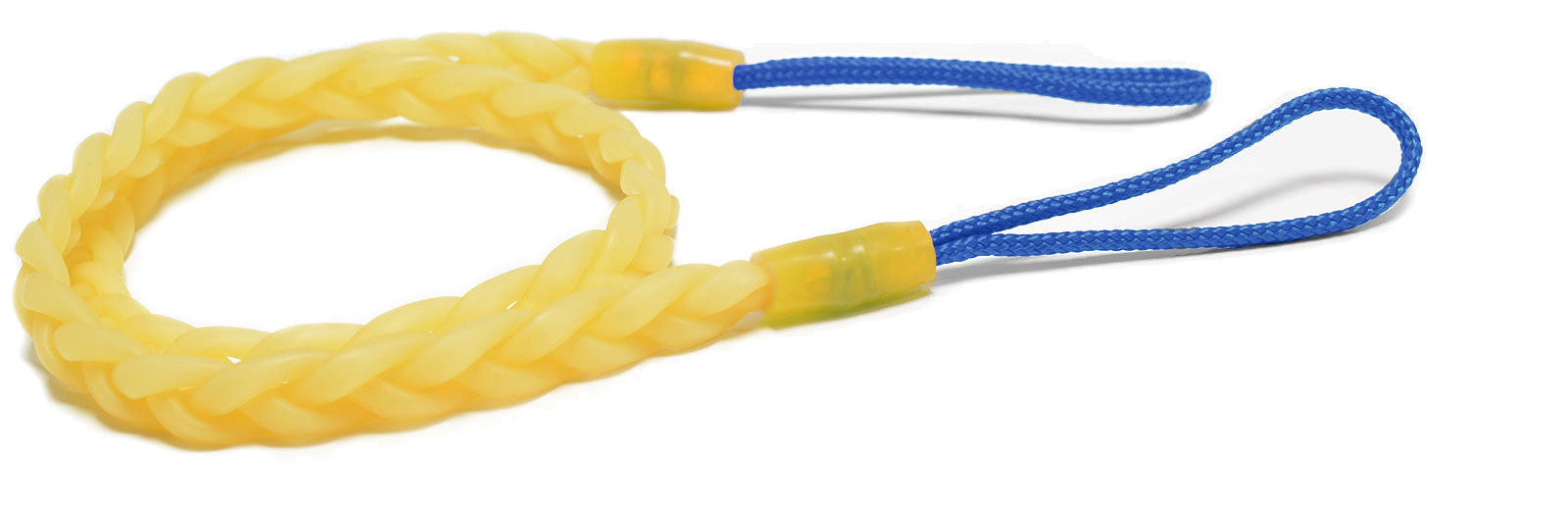
Flexo-Line Co. manufactures unique travel clotheslines which are flexible, lightweight, and easily packable clotheslines and do not require any clothespins. Flexo-Line’s clotheslines are used by travellers all over the world and are handmade in Burnaby, BC. Each Flexo-Line clothesline is made of 3 natural latex strands which are braided together and then fixed at the ends with versatile nylon loops. Flexo-line is a small privately owned company operating in Burnaby, BC.
About the Project
The Flexo-Line Company required a machine to create the natural rubber latex braids, in order to reduce repetitive strain injuries to their hands and meet increasing customer demand. Our client also specifically needed to use fixed length pre-cut latex strands because of the manufacturing limitations of natural latex. Our team aimed to design a machine that is portable, reliable, within budget, and easy to maintain. Most importantly, it had to create an even, consistent braid without twists or defects that would have compromised product quality.
I was immediately drawn to this project because it seemed to offer the perfect opportunity for me to use my mechatronics knowledge and experience to create an actual device which solves the engineering needs of a real-life client. I chose this project as my highest ranked choice and was lucky enough to be assigned to this project.
I worked on this project within a team of 3 other people: Marla McFee, Nadine Maurus and Tristan Kimberley.
Basic Operation of the Braiding Machine
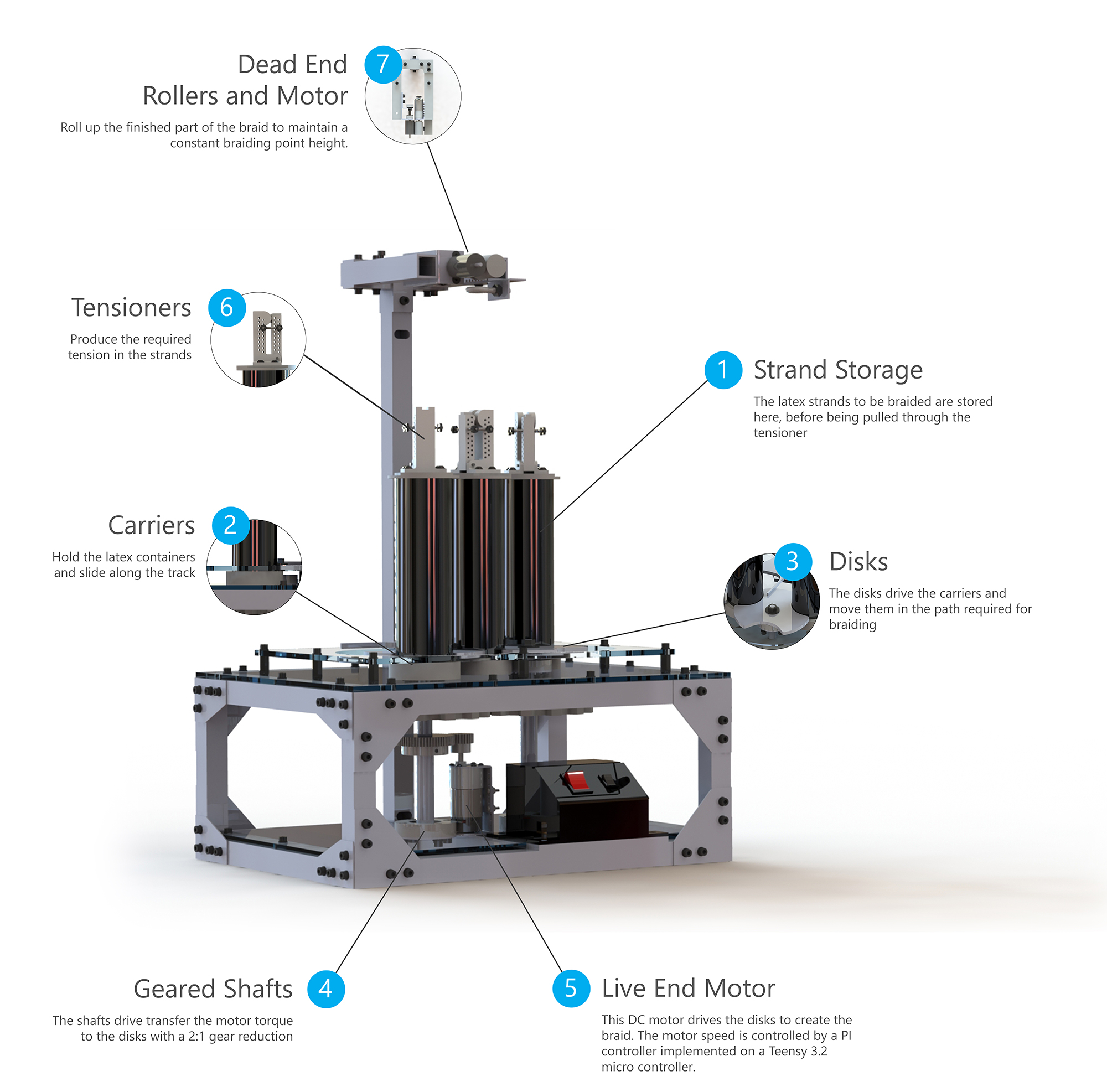
Through experimental testing and data analysis, we determined the relationship between braiding angles, tension forces and the resulting braid quality. Our solution is a braiding machine that maintains a constant angle while controlling the tension with spring-based tensioners and top end rollers. It uses a carrier-disk system to move the live ends, stored in tubes, in a figure 8 pattern around a track. This motion creates a braid that is then pulled up through the top end rollers as it is completed.
Initial Research and Conceptualization
In the beginning of the project, I worked together with my team to conduct research about any existing braiding solutions. However, we were unable to find any pre-existing solutions that could be used for fixed-length elastic strands and provide the consistent quality required by the client. Almost all of the existing solutions were designed to work with spools of inelastic fibers for creating long ropes.
This meant that we needed to create our own unique solution while borrowing ideas from existing solutions. We followed the proper engineering conceptualization process and carefully documented our function structure diagram, determinative functions, evaluation criteria, our concepts and our concept refinement procedure. We also held regular meetings with our client to keep them updated on our progress and to get a better understanding of their requirements.
Critical Function Prototype
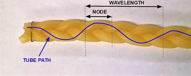
The factors which determine the quality of the braid were one of the biggest unknowns in our project. In traditional braiding machines which use inelastic strands, the tightness of the braid can be increased or decreased by increasing or decreasing the braid angle respectively (see figure 2).

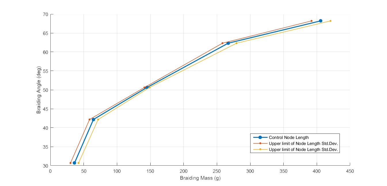
However, in our case, the strands were elastic and the tension in the strands also became one of the factors which controls the tightness of the braid. The tightness of the braid was likely to be directly proportional to the tension in the strand. The tightness of the braid was determined by measuring the nodal length of the braid (see figure 3).
To gain more understanding about our critical function, we created a simple test setup which would allow us to vary the tension in the latex strand and the braiding angle to create several braids.
Our client had provided us with 10 samples of ideal braids which we could use to define the ideal required nodal length / tightness of the braid. The nodal length of each braid created with a certain strand tension and nodal length in our experiment was also measured and compared to the ideal nodal length.
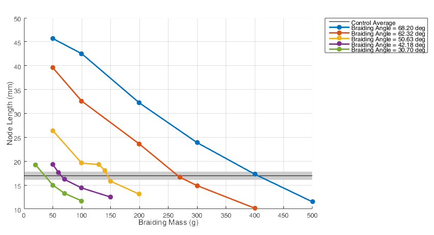
Using this data, we could design our braiding machine such that it maintains a certain combination of braid angle and strand tension that would produce a braid with the ideal nodal length.
3D Model of the Braiding Machine
At the half-way point of the project, we had enough data to start designing the braiding machine. I was in charge of designing and 3D modeling the:
- Overall frame of the machine
- Dead end mechanism (the top part of the machine)
- Flapper (the part which guides the carries from one side to the other as they pass through the centre of the machine)
- The overall assembly model for the machine
The Electronics
I also worked on selecting the motors and the control electronics for the machine. We used 2 DC motors with high internal gear ratios to provide high torque and low angular velocity. One of the motors was used for assisting the user in pulling up the finished part of the braid while the other more powerful motor was used to run the actual braiding motion on the live end of the machine.
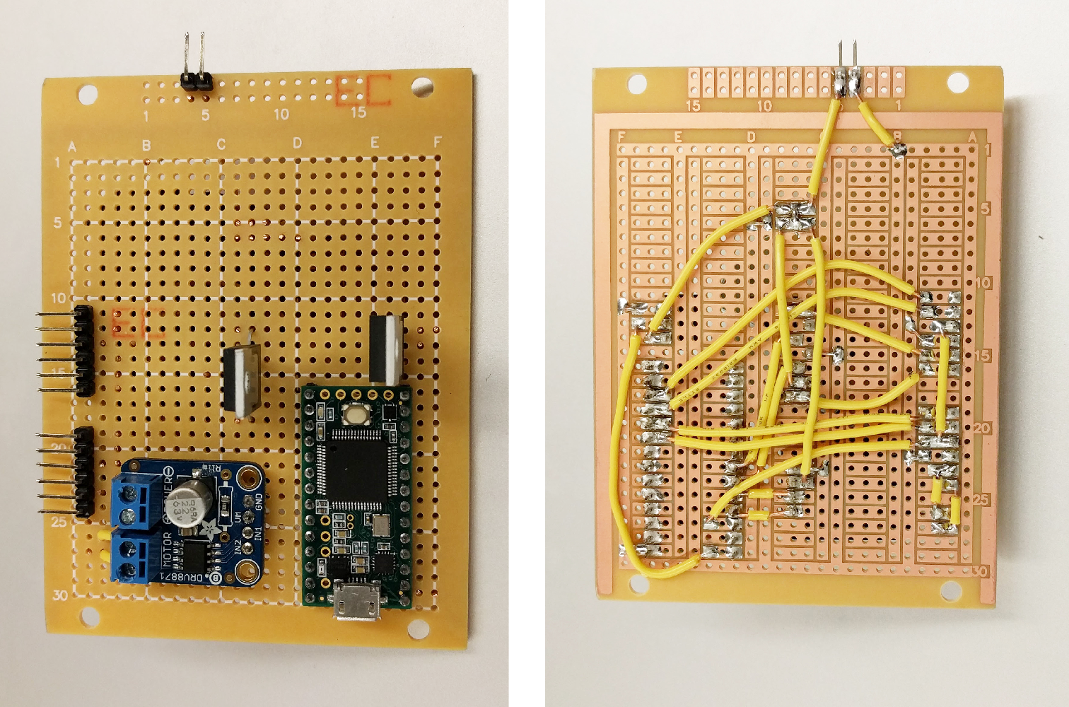
For our control electronics, we used a Teensy 3.2 as the microcontroller and two H-Bridge PWM motor controllers for each motor. The Teensy 3.2 was chosen because it can be programmed using the Arduino IDE and can be configured to output PWM signals with a 16-bit timer. This allowed us to have 65535 levels of control over the speed of the motors. All of the electronics for our project were selected to be through-hole so that they could be prototyped, adjusted or replaced more easily. I soldered the through-hole electronics on a proto-board and connected it to an AC to DC power supply.
The layout of the electronics board was designed to be easily replaceable or repairable in case our client runs into any issues in the future. The Teensy 3.2 is also easily accessible in case our clients wish to work with another capstone team to upgrade the machine in the future.
The Software
The software for the microcontroller was designed to maintain a constant desired motor velocity using a PI (proportional integral) controller. The MCU constantly measured the motor’s speed from the encoder integrated with the motor using an ISR (interrupt service routine). Based on the difference between the desired encoder counts (easily converted from desired motor speed) and the actual encoder counts, the duty cycle of the PWM signal is increased or decreased by the PI controller to keep the actual encoder count as close as possible to the desired encoder count. The continuous time PI controller was discretized and the controller constants were fine tuned to provide the best performance possible.
The MCU also continuously sends data packets to any device connected to its USB COM port. I also created a .NET C# program which could be easily used to record and analyze the performance of the motors in real-time.
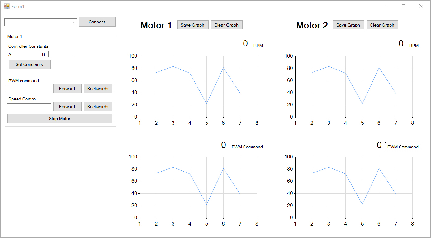
The motor speeds in the final version of the braiding machine were locked down and the machine could be turned on or off using a single switch so that the machine did not need to be connected to a computer in order to operate.